Version 28.5 = engineering R3.7. The package and film retain the R3.7 filenames. This candidate follows 28.4 / R3.6, whose printed case fitted the bare PCB but interfered once cables were connected. Publishing this page does not change the CAD.
Send this ZIP to the shop
One matched set. One of each product part and test fixture.
17
Rigid parts
Shells, controls, supported retainers and grille bezel.
2
Flexible parts
F01 bumper and F02 talk-button grip.
2
Clear optics
L01 lens and L02 periscope light guide.
Send to the print shop · 21 parts + 5 test fixtures
Walkie_One_R3_7_SEND_TO_PRINT_SHOP_2026-09-16.zip
ZIP · 12.9 MB
17 rigid, 2 flexible and 2 clear optical product parts. One of each test fixture. STL and STEP are alternatives, not duplicate quantities. Millimetres; 100% scale.
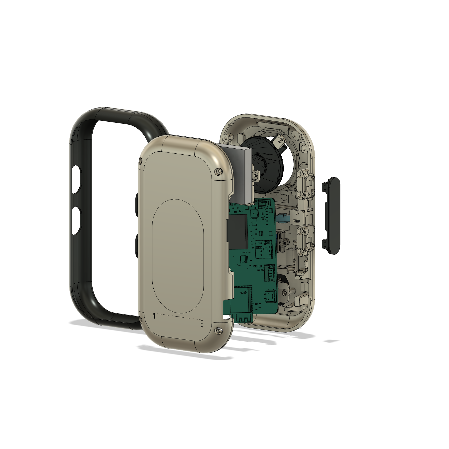
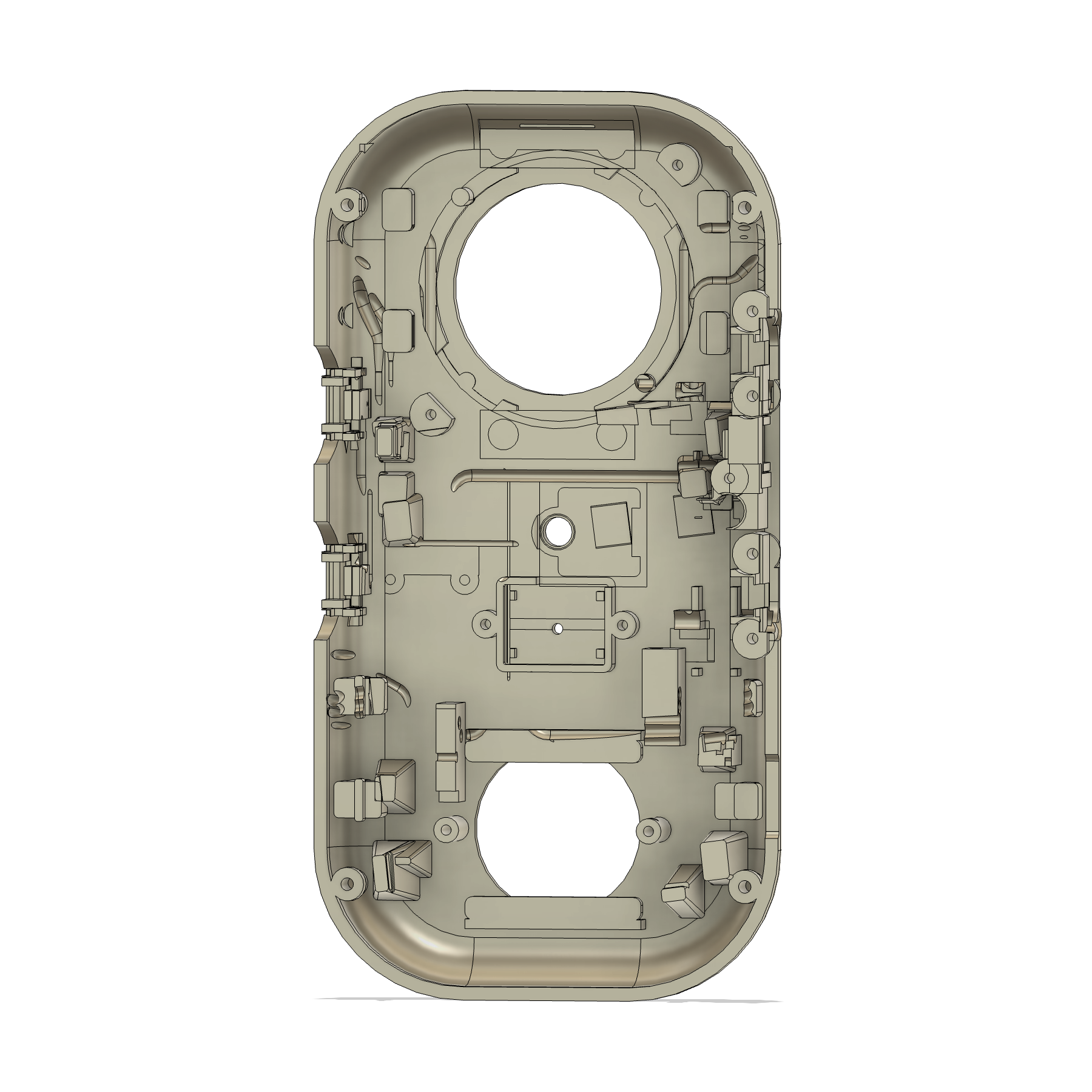
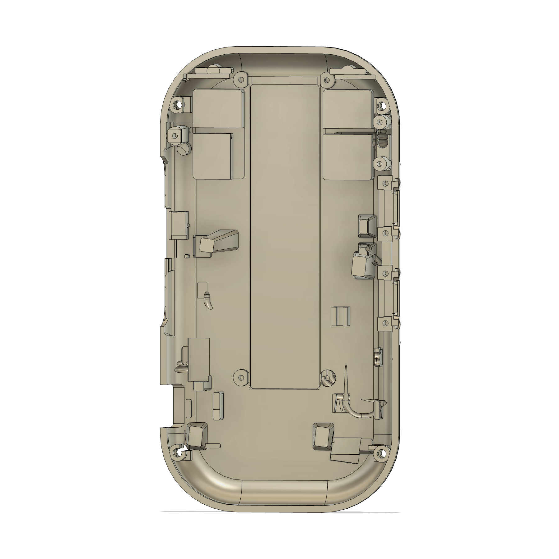
The ZIP separates the three material groups and five test fixtures, with individual STL files and matching STEP alternatives. Print either format once per item. It also includes clean reference images and owner assembly instructions. Temporary supports are chosen in the slicer; use the front/rear shell diagrams to identify permanent features before removal.
Record the shop’s material, orientation and finishing. Use the supplied joint, battery, PTT and screw-pilot fixtures to check this print process. No printer profile or G-code is supplied.
Simpler inside, with all connections considered
Compared with 28.4: 28 → 21 printed parts · 32 → 22 screws · 11 → 4 PCB pads.
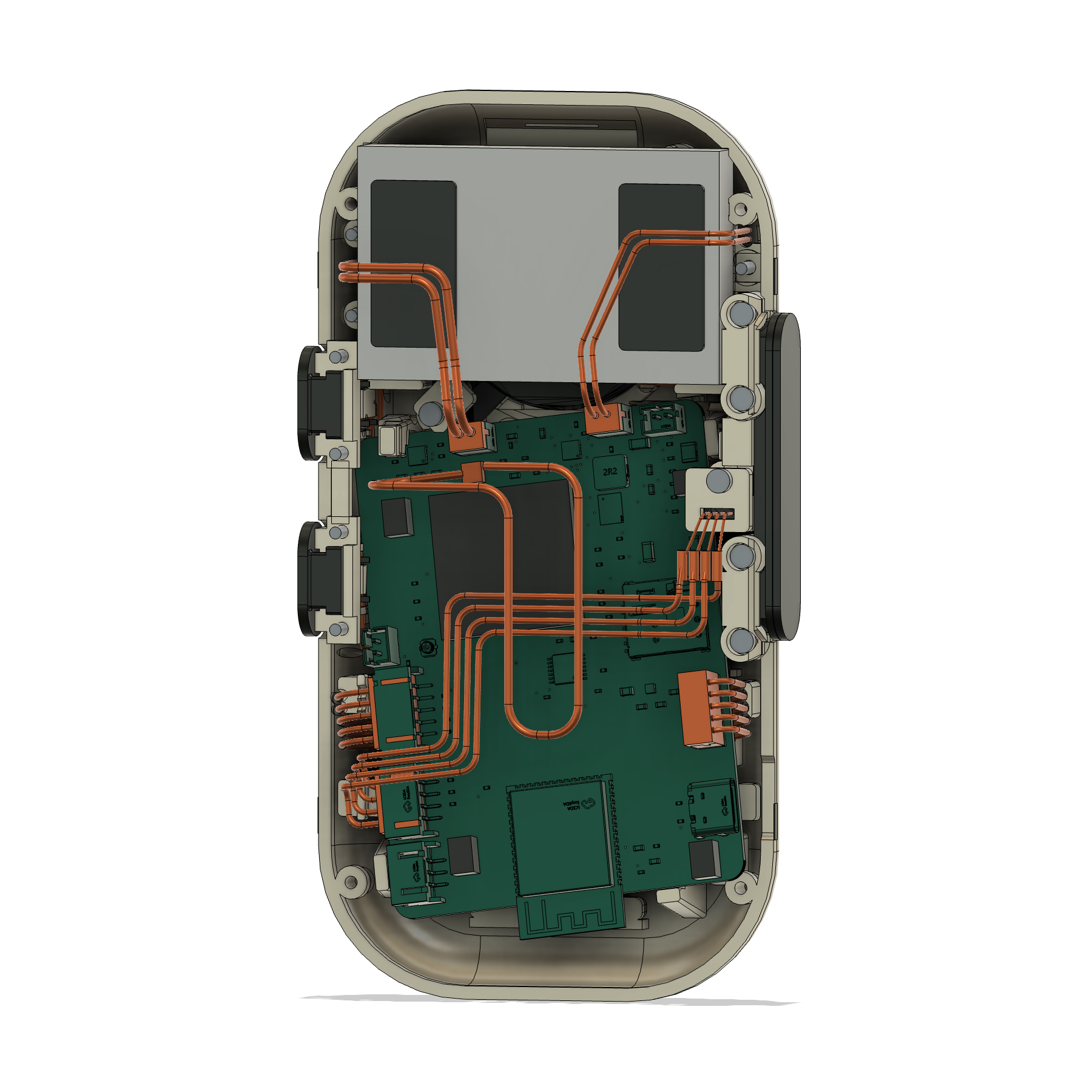
Connected PCB
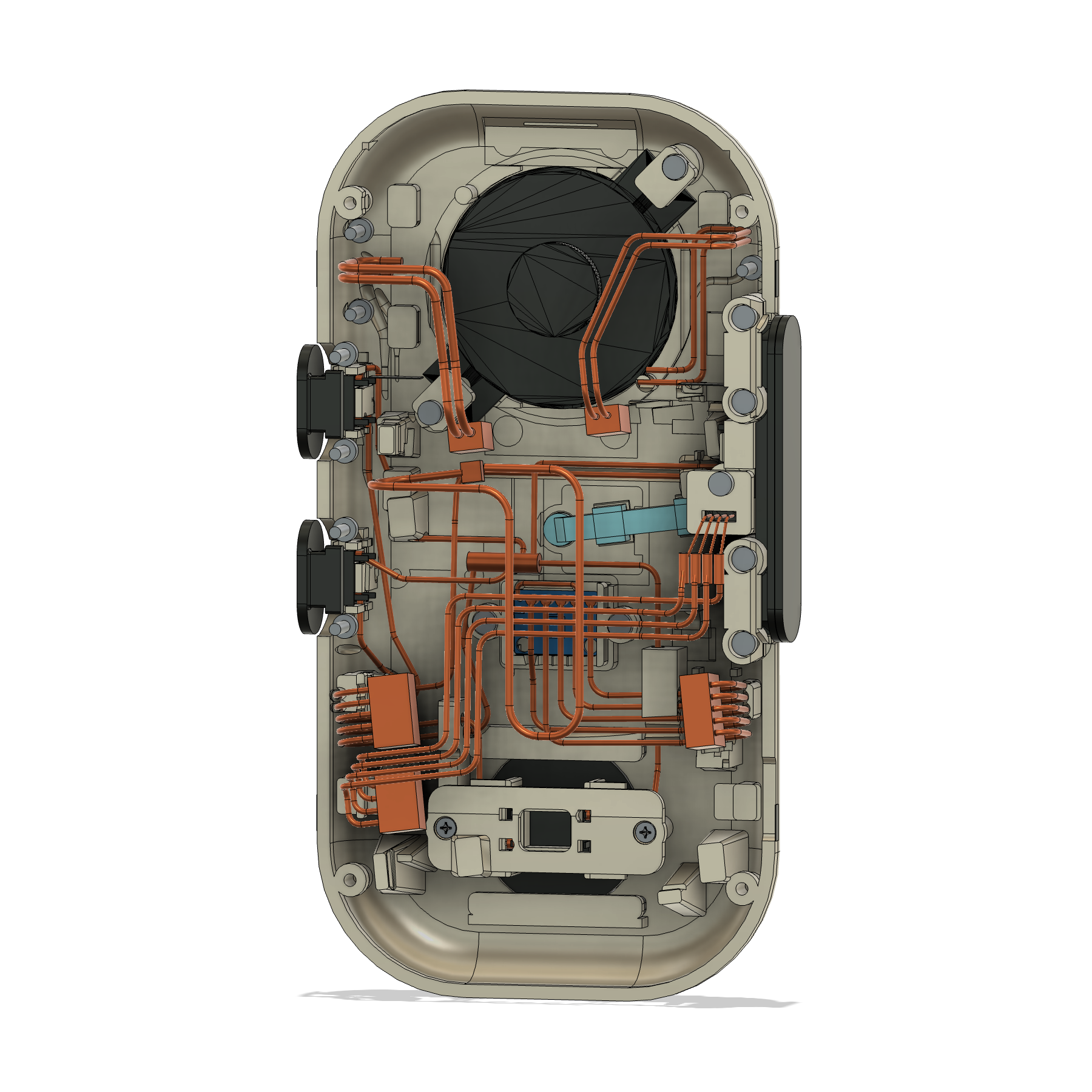
Make room for the plugs and wire turns
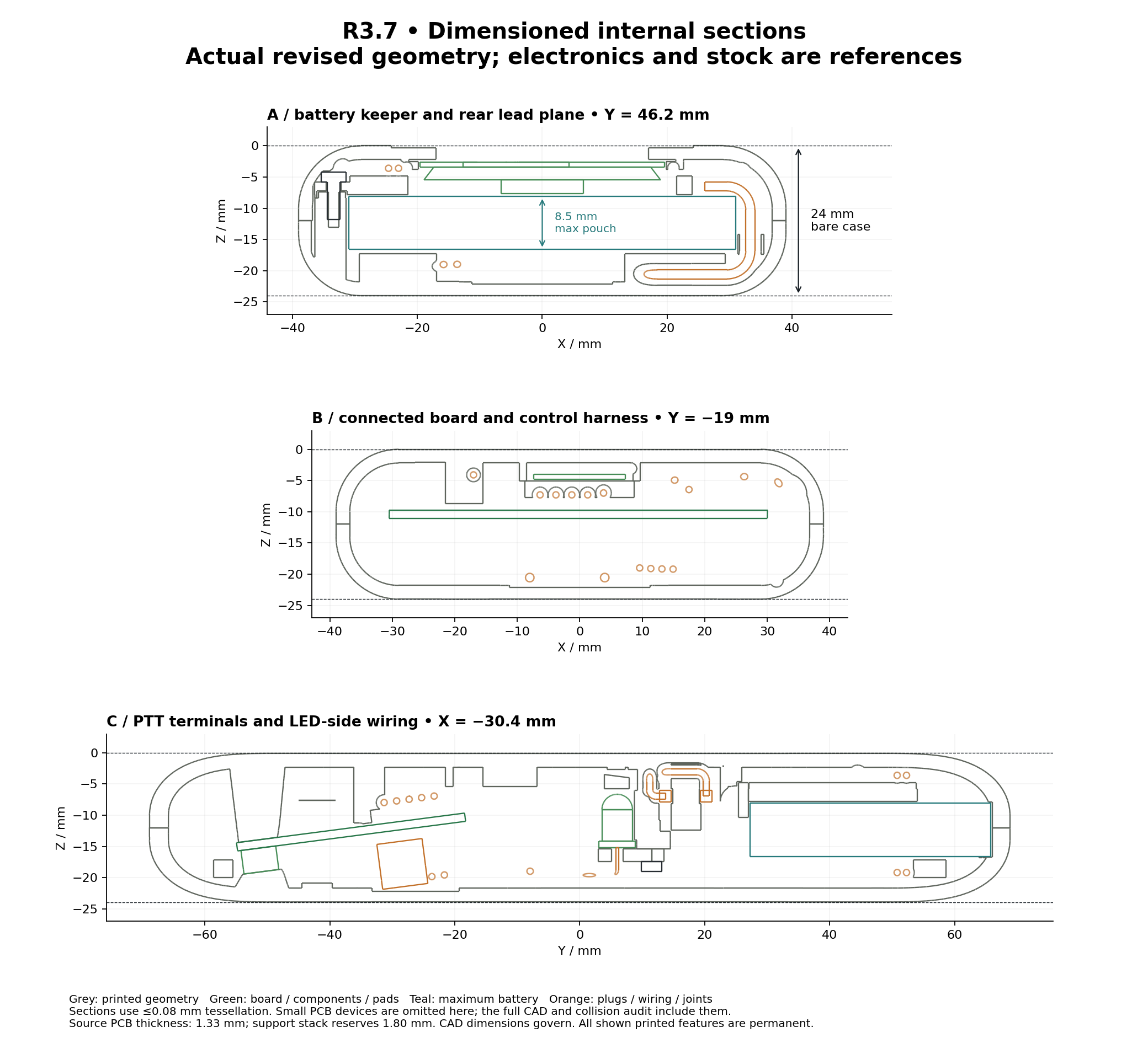
The PCB moves and tilts inside the existing shell while retaining the USB opening. Plugs, insulated joints, bends and wire-dressing space are included together. Four paired pads support the board, and a broad stop takes connector insertion loads.
Battery
Direct factory connection
The custom battery adapter, cover, grommet, pads and fasteners are removed. The untouched factory plug goes to J2. Low locators and broad removable keepers retain the 62 × 38.5 × 8.5 mm maximum battery body; a central bay reserves room for the factory lead slack.
Controls
Fewer pieces around the same moving buttons
Three loose switch cradles become supported seats in the shell. One removable volume rail captures two independent sliders with their own stops. The broad PTT and play mechanisms remain; short separate PTT guides leave the wiring corridor open.
Speaker and microphone
Keep terminals and wired parts accessible
The speaker rotates 45° around its unchanged acoustic centre. Two short keepers retain access, with a shorter recessed upper screw. The blue SPH0645 microphone has an open keeper for its low-profile joints and channel-select jumper.
LED and optics
Route the light to the original opening
The LED sits beside the PCB. A clear periscope light guide carries light to the original lens. Both optical parts need clear material and suitable finishing; opaque prints can check fit but cannot qualify the indicator.
Antenna and soft stock
Remove handling steps that add little value
The antenna uses its factory adhesive on a thin dielectric carrier, removing two clamps, four screws and old end pads. PCB pads reduce from eleven to four; three obsolete switch-cradle backing films are removed. Adhesive and soft-stock thickness remain specified.
Every retained, integrated, combined or removed part has a recorded disposition. The review also covers fasteners, purchased components and installed stock, with 156 feature-level risk entries.
Build the wiring this layout expects
Prepare the harnesses before assembling the print.
The microphone cable is a required change
Use the JST 05KR-D6S-P transverse-exit PH-compatible plug, professionally IDC-terminated with 26 AWG, 7-strand UL1061/UL1571 wire, 0.9–1.0 mm outside diameter. The design uses its 9 mm catalog mated envelope. A tall upright PHR-5 plug or a different housing does not represent this layout.
The speaker, buttons and LED use shortened flexible 28 AWG UL1061 wire, 0.8–1.0 mm outside diameter, with the specified PHR housings and SPH-002T-P0.5S contacts. Keep the battery and RF factory cables intact. No main-PCB solder changes or battery-adapter board are required.
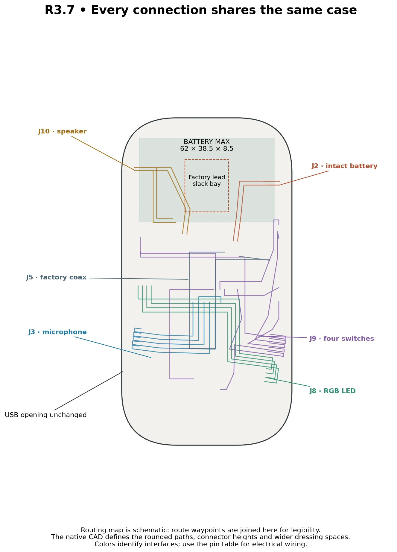
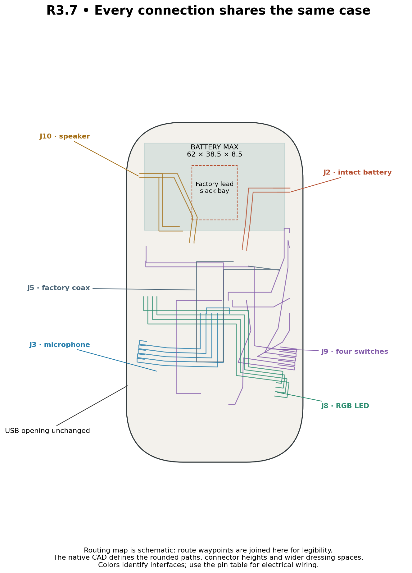
Battery · J2
Factory plug, protected exit, natural bends and a separate slack bay. Factory cable and battery wrapping stay intact.
Microphone · J3
Five-way transverse-exit plug, five wires, low-profile insulated joints and the SEL-to-ground jumper on the blue SPH0645.
Speaker · J10
Two-way plug, one-piece leads and speaker-terminal exits. No inline splice in the fitted route.
Four buttons · J9
Five-way plug, four signal paths, a shared return junction, switch branches and insulated joints.
LED · J8
Four-way side-entry plug, wire turn, individually insulated LED leads and the clear light guide.
Antenna · J5
Mated RF connector, the full factory coax route and the installed antenna.
USB · J7
Original case opening and external cable insertion. The 11.5 × 6.5 mm shoulder envelope is a design limit; actual cable seating remains a physical check.
Schematic routing, not a colour-based pin map. The harness document specifies contacts, pin mapping, initial wire blanks, insulated joints and bench-dressing allowances.
Continuity-test every harness and verify switch terminal pairs before connection. LED J8 pins [1, 2, 3, 4] map to physical LED leads [1, 4, 3, 2]. Initial wire blanks include termination allowance; dress the destination end before final trimming.
4 min 32 sec · Narrated CAD walkthrough · English captions.
Actual CAD, assembly photos, internal sections and an exploded view explain R3.7. The film distinguishes completed digital checks from physical testing still to come.
Connected fit explained · 4 min 32 sec
Walkie_One_28_5_R3_7_Chalk_Ember_Explainer.mp4
MP4 · 14.9 MB
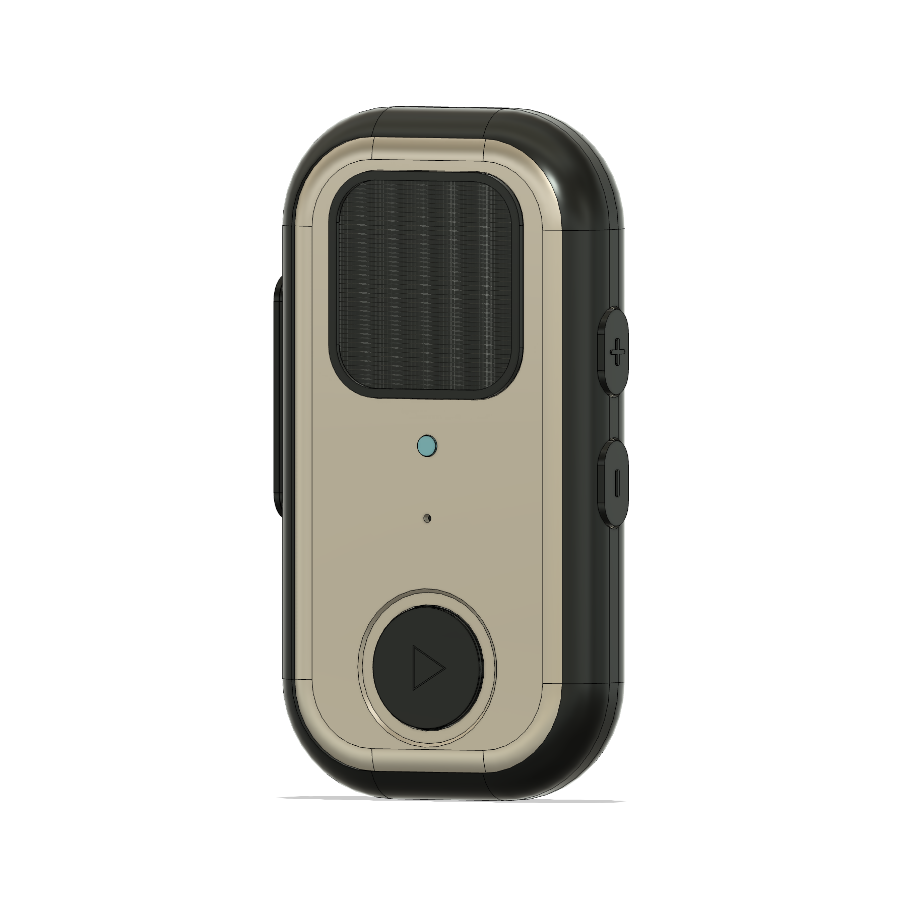
Actual CAD in the light Chalk Ember finish, with narrated reasoning and remaining physical checks. R3.7 geometry and narration are unchanged.
The original 84 classified shell faces, openings, seam and external components were compared. Final support changes remain inside the protected exterior. Nominal bare-case dimensions stay 78 × 150 × 24 mm.
Matched CAD and meshes
All 21 STL files are closed, consistently wound and single connected bodies. They match the individual CAD solids. The native Fusion archive was reopened and all 21 print identities verified.
Connected assembly
All seven interfaces and wider wire-dressing volumes were reviewed together. No unresolved modeled rigid, hardware/electronics, physical wire/part or wire-pair interferences remain. Forty-five retained installed-stock groups are represented.
Motion and fastening access
28 travel samples, 32 edge-rocking probes and six paired-control cases were checked. All 22 fasteners have staged access checks with a 3 × 30 mm driver shaft. Actual switches, tools and assembly still need a physical trial.
These results depend on documented connector, joint, stock and wire envelopes. Local load calculations are diagnostic screens, not process-specific strength certificates. CAD clearance does not establish print strength, cycle life, sound, light output or radio performance.
Use the R3.7 set together. Original engineering filenames and file checksums are preserved.
Send to the print shop · 21 parts + 5 test fixtures
Walkie_One_R3_7_SEND_TO_PRINT_SHOP_2026-09-16.zip
ZIP · 12.9 MB
17 rigid, 2 flexible and 2 clear optical product parts. One of each test fixture. STL and STEP are alternatives, not duplicate quantities. Millimetres; 100% scale.
Use individual parts for printing. The full STEP is an engineering reference containing purchased components and clearance gauges; its external USB gauge is intentionally retained.
Editable native Fusion CAD
Walkie_One_R3_7_CONNECTED_PROTOTYPE.f3d
F3D · 25.8 MB
All 21 print identities verified after reopening. External USB fit gauge is hidden by default.
Follow the supplied assembly order and screw-length schedule. Fit the already-wired switches and internal fasteners while their access is open. Use the bare-shell diagrams when removing print supports.
Install the battery, microphone, speaker, button harness, LED and antenna together. Dress natural wire bends and factory slack without forcing connectors, bowing the PCB or pressing on the pouch.
The case must seat by hand before tightening. Then confirm USB fully seats and each control operates at its centre and edges, including both PTT ends and simultaneous presses.
Complete 10 assembly/service cycles and 1,000 actuations per control. Inspect for cracks, deformation, loosening, binding, unintended activation and wire pinching.
Record electrical, charging, acoustic, optical and RF results. Review the received cable envelopes, foam compression and print-process tolerances alongside the fit results.
Physical qualification is still pending. Golden promotion is a separate decision after those results.