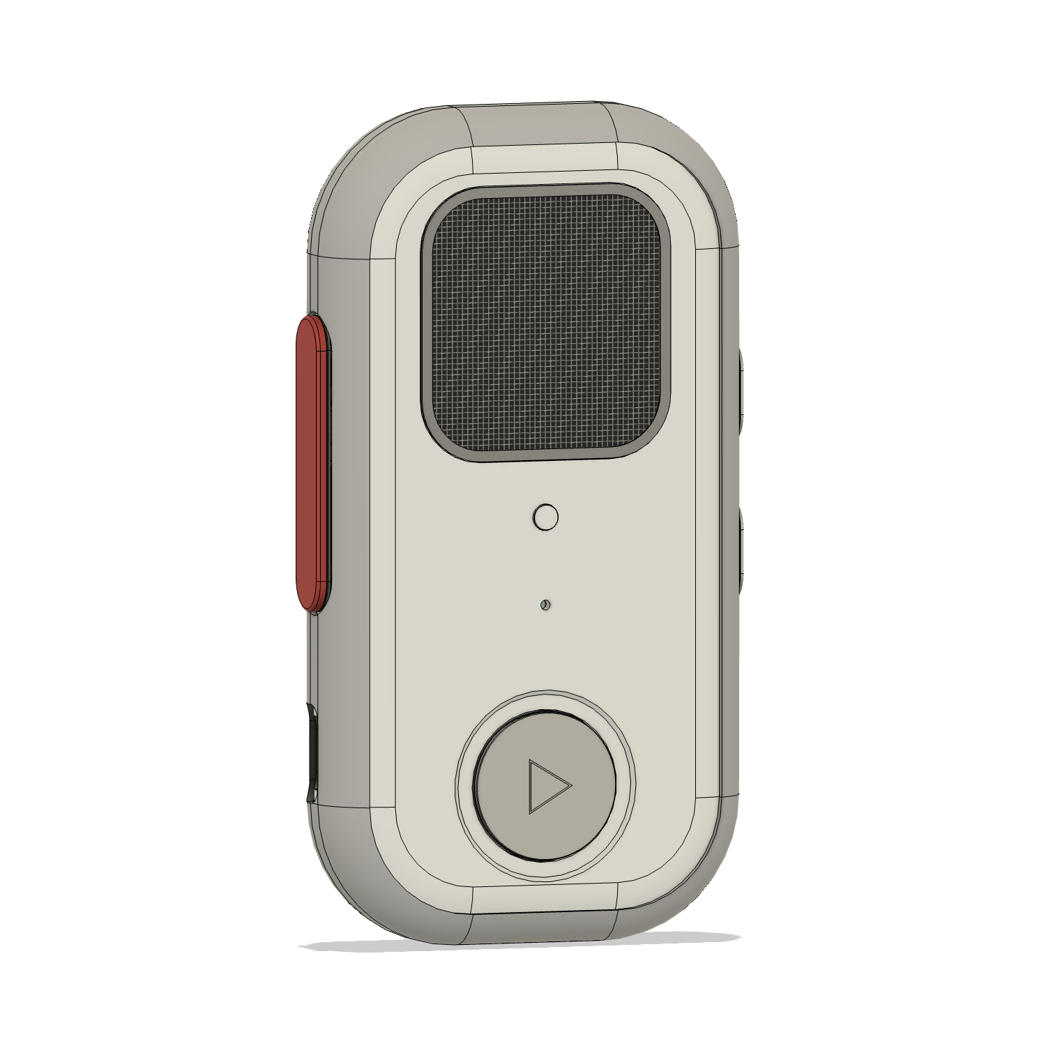
R3.2 A supplies six changed or new parts. Reuse unchanged parts from R3.1. The candidate is for fit and functional testing; the frozen R3.1 package remains the RPS baseline.
From the supplied Fusion model
Build views.
Inspect the exterior, cable route and removable PTT guides.
R3.2 A keeps the Chalk Ember shell, soft rim, orange grip, round play cap and lowered status light.
R3.1 → R3.2 A
Two internal changes.
01 / Button guidance
A guided press-to-talk carrier
Twin Ø2.4 mm pins run in 24.7 mm split guides. The front shell forms one half; two removable caps close the other half after rear insertion. Nominal bores are Ø2.6 mm, with 0.2 mm diametral clearance.
The inherited contact, switch cassette, 0.15 mm released gap and 0.45 mm stop travel remain. Two additional M2 × 5 guide-cap fixing references need an agreed fastening process.
02 / Antenna integration
A complete coax route
The existing Taoglas FXUB63.07.0150C antenna retains its position. Its nominal 150 mm cable runs through a relieved lower frame with a dielectric bridge, then into two open rear-shell saddles with tape lands.
The package checks routes at 141, 150 and 159 mm. The proposed 5 mm bend radius, plug seating, tape retention and antenna metal spacing still need physical confirmation and RF testing.
Prototype scope
Build and check the changed interfaces.
Print the six replacement parts, reuse the unchanged R3.1 pieces, and assemble with the real switches and antenna. The STL files retain assembly coordinates: orient, support and slice them before printing. They are not complete P1S printer projects.
1. Fit the guides
Insert the PTT carrier from the rear with both caps removed. Check pin and bore finish, then fit the lower and upper caps before the PCB. Confirm the pilot, fastening method and torque with RPS.
2. Dress the coax
Follow the lower-frame relief and rear saddles. Fit dielectric retaining tape and confirm the actual feed, connector, bend limits and service slack. Inspect for pinching with the rear cover closed.
3. Test the closed case
Measure the real switches and check electrical make, release and return at the center and both ends. The supplied notes suggest 100 distributed presses as an initial screen, not a qualification standard.
Still to qualify
Actual switch travel and force; antenna installation and RF performance; the missing detailed U6 model and populated PCB fit; wiring, acoustics, indicator light performance, resin and fasteners. R3.2 A is not a production or casting release.
R3.2 A / original source files
CAD, print parts and notes.
The complete ZIP contains all 32 supplied files. The native Fusion model and full STEP assembly include purchased parts and reference envelopes. Use the six individual changed-part files for the prototype.
Complete native Fusion candidate
Walkie_One_28_R3_2_A_PTT_RF_PROTOTYPE.f3d
F3D · 20.3 MB
Editable R3.2 A assembly. Purchased parts and review envelopes remain reference geometry.
The supplied independent report records 568 valid assembly solids, six valid changed-part STEP solids and six watertight STL meshes. It reports no positive PTT overlap at five sampled straight-travel positions from 0 to 0.45 mm. These are nominal geometry checks, not physical qualification. Website preparation verifies the supplied bytes and checksums; it does not rerun CAD simulation.
The supplied R3.1 package contains the unchanged parts, nine-page RPS handoff, materials and finish targets, 93 fabricated STEP groups, five Bambu projects, 24 print meshes and 14 cutting DXFs. Use its printer projects for the unchanged baseline pieces and the R3.2 A replacements above for this candidate.